Electric Loco Tap Changer Operation
by Khalid Kagzi, October 2005
On this page
- Introduction
- Power Supply
- Tap Changers
- ABB N32 Tap Changer
- Air Servo Motor
- Auxiliary Cam Group Switches
- Relays
- Push-button/Manual Operation
- Selsyn Notch Transmitter/Indicator
- Photographs
- Additional Diagrams
Recently I had the chance to visit the Electric Loco Shed at Valsad, and I had the opportunity to shoot a lot of pictures, some of which were of the tap-changers (tapchangers) used in electric locomotives. Below is a write-up on tap-changer operation.
Introduction
On the Indian Railways, a large number of electric locomotives are in operation today. Many different models of these locos have been manufactured, many of which have now been scrapped. However, many of those models which are still in service such as the WAM-4, WAP-4, WCAM-1, WCAM-2, WCAM-3, WCAG-1, WAG-5,WAG-7, etc., use almost the same electrical setup (excepting the newer 3-phase AC locos such as the WAP-5 and WAG-9).
In traction duty,the basic characteristics of the traction Vehicle should be such that it can exert a high torque during the starting phase and gradually the torque should decrease and the speed of the vehicle should increase.
These characteristics are obtained in electric locos on the Indian Railways by the use of the series-wound DC traction motor which has an inherent characteristic of exerting a high torque during its starting phase and a high speed during the running phase when the train resistance is minimal.
However in order to have proper speed control over these traction motors the voltage supplied to these motors must be varied. Increasing the voltage to the motor increases its torque and speed and vice-versa.
This variation of voltage is obtained by the use of an on-load tap-changer in the locos.
Traction Motor Power Supply Overview
Before explaining the working of the tap-changer provided in these locos, it will better if the broad outline of the power circuit of these locos is understood properly.
These locos operate on a nominal voltage of 25,000V AC (single phase). The power is supplied from the overhead equipment (OHE). This power is collected from the OHE by the pantograph which then passes it to the main circuit breaker (DJ). From the DJ the supply is fed into the main transformer through a high tension bushing. The transformer is actually composed of two different transformers which are wound on the same steel core. This reduces space requirement and also provides better magnetic coupling.
The first transformer is an autotransformer with around thirty one tappings which are brought out to the tap-changer. The output voltage of the autotransformer depends on the tap at which the selector of the tap-changer is resting. Hence,by changing the position of the tap-changer selector the output voltage of the auto-transformer can be varied conveniently. The Tap-Changer is provided on the high-tension side of the transformer which reduces its size due to the lower current. Insulation is enhanced by filling the selector casing with oil.
The output of the autotransformer is fed to the second transformer which has a fixed ratio and steps down the voltage to a fixed fraction. The output of this second transformer is then fed to the rectifier blocks (RSI 1 and RST 2). These convert the AC into DC. In turn the DC output is fed into a pair of chokes known as smoothing reactors (SL 1 and SL 2). The smoothing reactors are provided to remove the AC ripple which is left over from the rectification cycle.
This smoothened DC is then handed over to the DC switchgear for the line and combination control of the traction motors and then finally to the traction motors themselves.
The subject of this article is the detailed manner in which the above mentioned tap-changer works.
Tap Changers
Before going into the details of the actual tap-changer which is used in the Indian Railways locos, it will better to understand in general what tap-changers are.
The output voltage of a transformer varies according to the turns ratio of the primary and the secondary windings of the transformer. It can appreciated that at any point of the primary or the secondary winding the voltage is different from any other point on the same winding because these points are at different ratios with respect to the other winding.
Hence each and every tap brought out from the winding gives a different voltage.
Broadly tap-changers can be divided into two categories-namely off-load and on-load.
Off-load tap-changers cannot be operated while current is flowing in the circuit. Off-load tap-changers are used mainly for non-critical applications where a momentary interruption in the current can be tolerated. Hence, such tap-changers have no use in traction duty.
In traction only on-load tap-changers (OLTC) are used. They are capable of changing the taps rapidly without interrupting the flow of current.
The Asea Brown-Boveri N-32 Tap-changer
Although there are many types of OLTCs, the one mainly used on the Indian Railways locos has been designed by Asea Brown Boveri and even today is known as the Brown Boveri type N-32.
This model is a huge success and is used on all the locos which I have mentioned in the introduction.
The general requirements and constraints encountered while designing an OLTC should be clearly understood before going into the specific design of the N-32 type Tap-Changer. This will also help in understanding the manner in which these have been dealt with in the N-32 type Tap-Changer:
- While the tap is being changed the output current must continue to flow.
- Any two taps must never be directly shorted because the existence of different voltages on the taps causes short-circuit level current to flow between the taps which in addition to damaging the tap-changer can also cause severe damage to the transformer.
- The tap-changer must be able to operate frequently without requiring extensive maintenance
The N-32 tap-changer has been designed keeping in mind the above mentioned requirements.
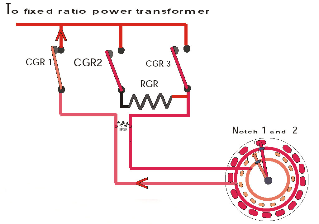
In the N-32 Tap-Changer all taps are terminated on a circular contact plate (see Fig. 1) with two concentric circles of contacts. In addition their are two contact rings surrounding the contacts. Two selector arms rotate over the contacts and the rings. One arm provides a short between the outer contact segments and the outer contact ring and the other selector arm provides a short between the inner contact segments and the inner contact ring.
These contacts rings are connected to the transition contactors CGR1 and CGR3 respectively.
In addition a resistance (RGR) is also provided which is inserted momentarily during transition from one notch to another. This insertion and removal of the resistance is carried out by the central contactor CGR2.
Operational details of the N-32 have been described beside each of the diagrams.
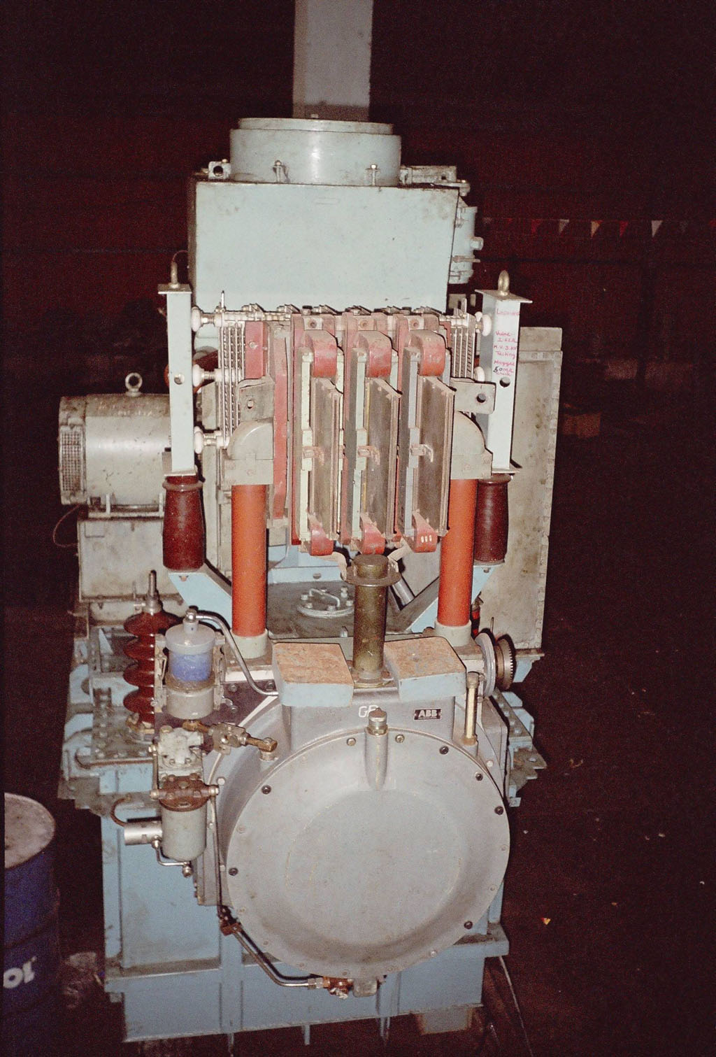
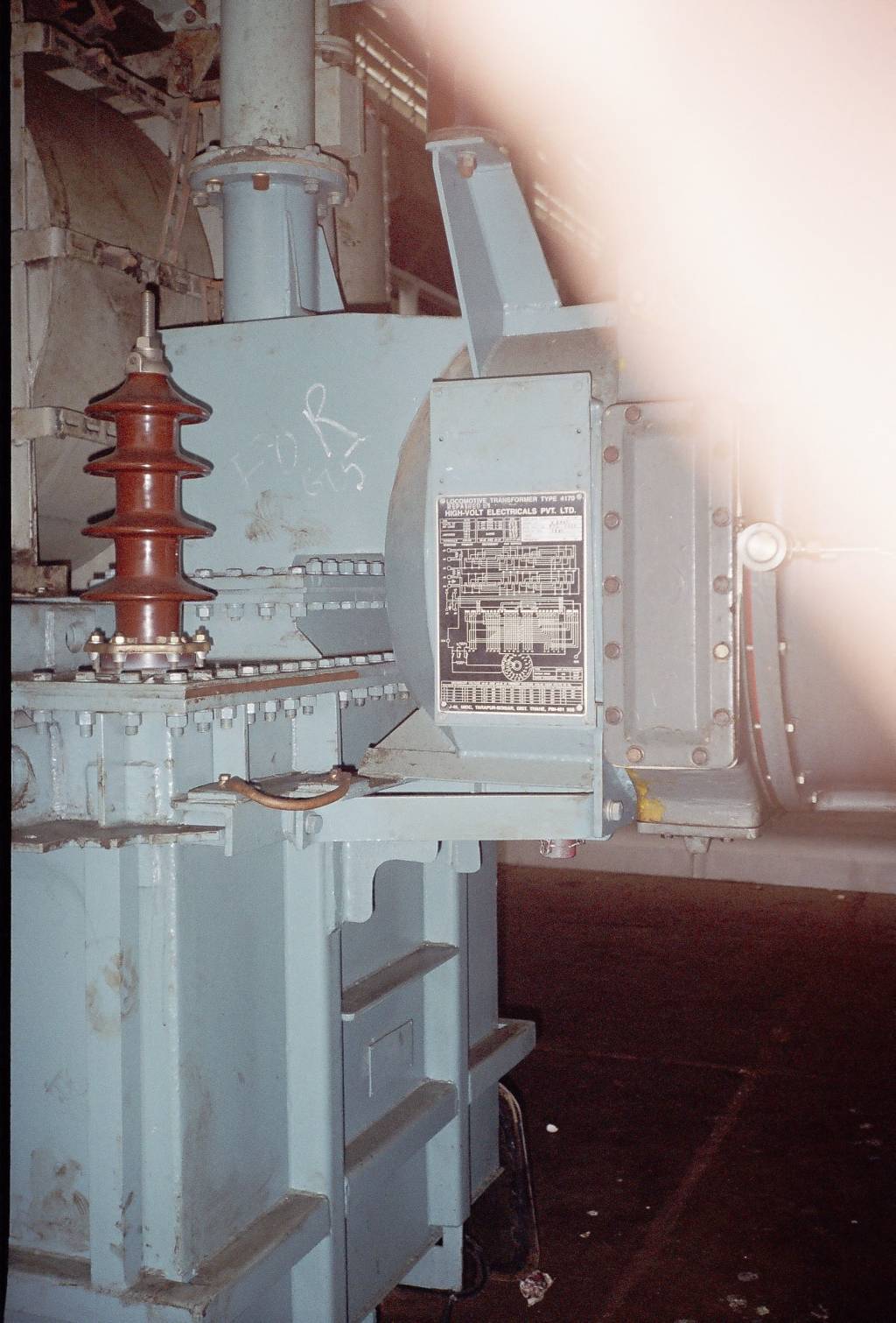
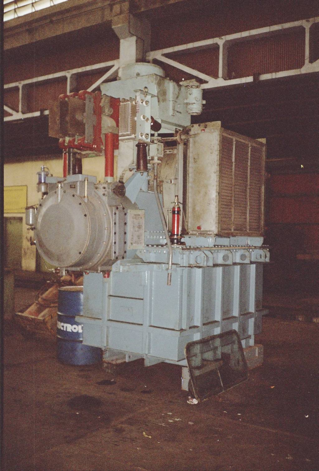
In this picture the Transition Contactors (CGR 1, 2, 3) and the Transition Resistance (RGR) as also the selector drum of the Tap Changer are visible clearly. The slotted elements behind the CGR contactors is the RGR. In the front the small cylindrical device with a bluish color with a pipe coming out of its top between the selector drum and the CGR block is the PHGR. The PHGR is a small pump operated by compressed air and is used to circulate the oil in the selector drum. This is done in order to remove impurities which occur in the oil due to particles breaking off from the selector arms and the tap segments due to frequent operation as also nominal arcing occurring during switching. To the right of the Selector Drum a small gear wheel is visible. This is the gear which connects with the Air Servo Motor (SMGR). This motor has been removed from this unit. The SMGR is an interesting study in itself. The shaft of the gear mentioned above is connected to a mechanism in the tap-changer body which operates the selector arms in the drum as also the CGR contactors in a pre-determined and closely co-coordinated sequence. The CGR contactors also have a common drive shaft with rotating cams which ensure that the CGRs operate in their proper sequence.
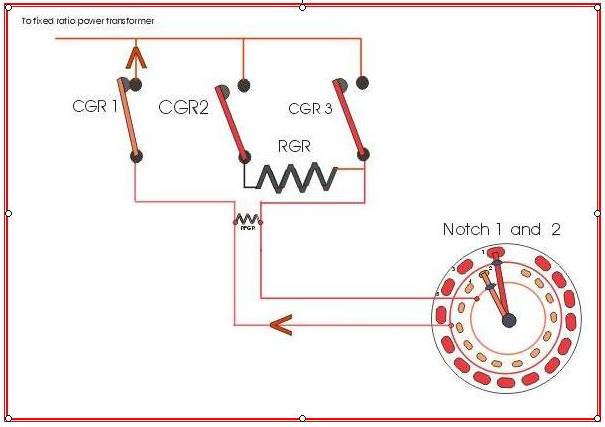
In the above figure the tap-changer is shown at the position of notch 1 and 2.But its supplying only to notch 1.The long selector is at tap segment 1 which in turn is supplying to the outer contact ring while the short selector is at tap segment 2 and is supplying to the inner contact ring.This ring is connected to CGR3 which is open. During transition from notch 1 to notch 2, CGR2 closes first which brings the RGR into the circuit. Here I should point out that the RGR serves two purposes, first of which is to ensure that when two taps are to be connected together it is done through this resistance which tends to limit the short circuit current which occurs when any two or more taps are connected with each other. Second purpose is to ensure the continuity of supply to the Traction Motors which is carried through the common link above the three contactors.
But a conflict arises while determining the ohmic value of the resistance RGR. If the resistance is too low then when the taps are shorted the short-circuit current would rise to unacceptable levels and if the resistance value is too high then the output voltage would be too low during transition which may cause a jolt when full voltage is restored. Hence,the ohmic value of RGR has to be a compromise between these two extremes.
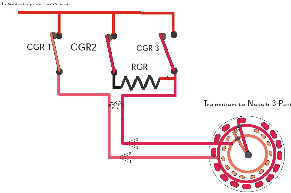
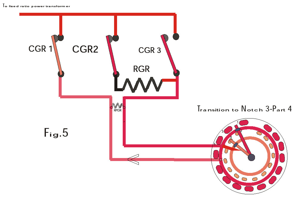
Now, coming back to the transition from notch 1 to notch 2, CGR2 closes first then CGR1 opens and then CGR3 closes thereby completing the transition. But here you will note that during the transition the selector arms have not moved. As soon as CGR-3 closes the long selector moves to tap segment 3. (See Fig. 2.)
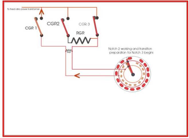
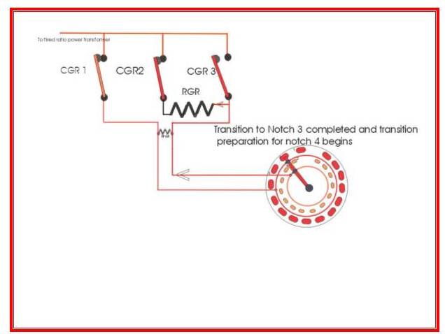
Fig. 2 describes the first phase of transition to notch 3. As CGR-1 is open, no current is flowing through the long selector hence it can move freely between the contacts without causing arcing. As soon as the long selector arrives at tap segment 3 the tap-changer is ready for transition to notch 3. Transition from notch 2 to notch 3 takes place on lines similar to that of the transition between notches 1 and 2. CGR-2 closes then CGR-3 opens and then CGR-1 closes.
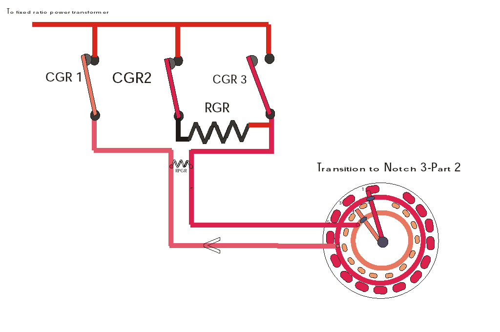
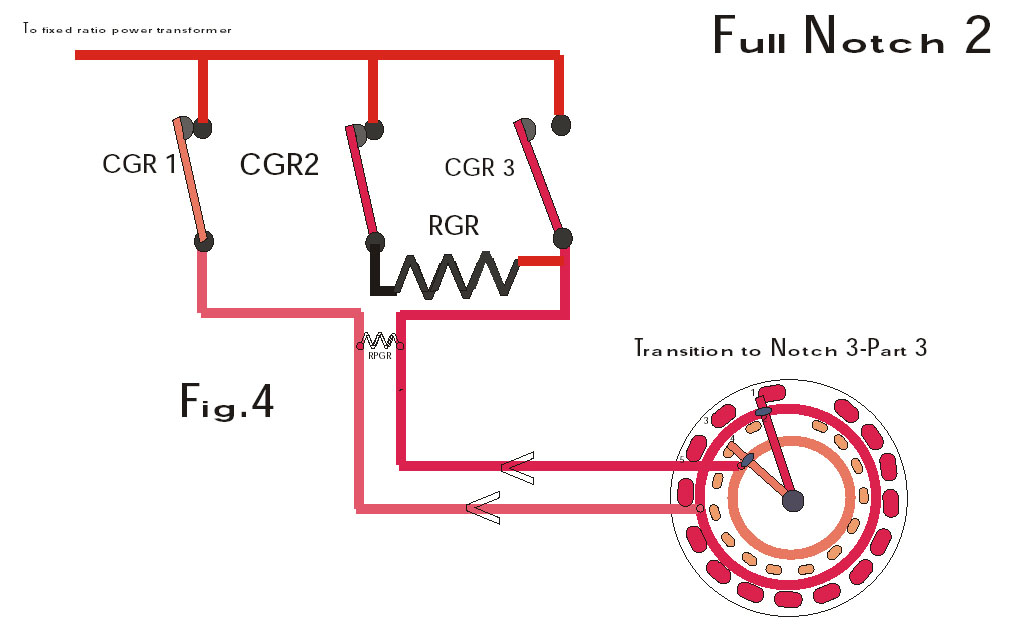
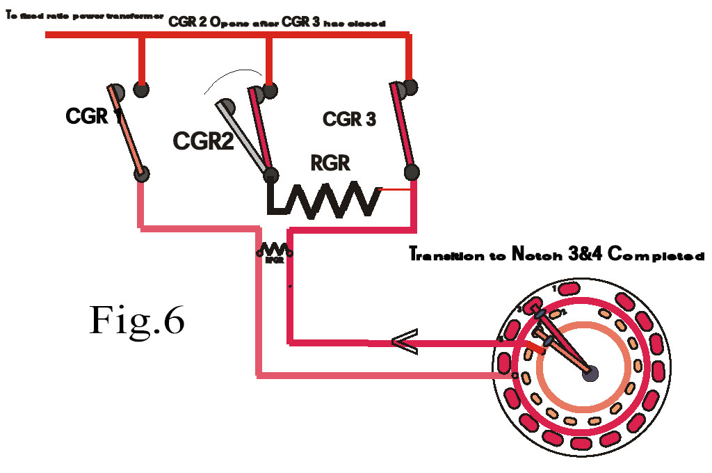
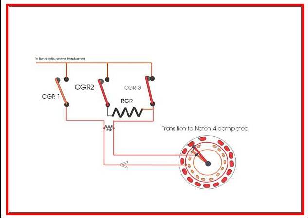
As soon as transition to notch 3 is complete the short selector moves to tap segment 4 hence making the tap-changer ready for transition to notch 4. Again the short selector moves while CGR-3 is open so that there is no danger of arcing. (See Fig. 3.) When the short selector arrives at the tap segment 4, transition to notch 4 occurs on lines similar to that of the transition between notches 1 and 2.
Rest of the notches also undergo transition as per the above description. During regression the exact reverse of the transition sequence described above takes place. Although the mechanical process seems to be cumbersome, it's actually very smooth because the basic design is simple and the mechanism is usually well maintained and lubricated with graphite grease.
The efficiency of the tap-changer can be gauged from the fact that it can operate upto a hundred or more times during a single run of the loco.
As per CLW specifications, the tap-changer must be able to complete a full cycle from first notch to the thirty-second notch in 11-13 seconds and similarly for regression from 32 to 0.
As I've mentioned above the tap-changer is very efficient and smooth but even the best maintained machines sometimes fail. As such in case of failure of any component of the tap-changer it must be ensured that the damage is curtailed as much as possible. For this purpose a series of protective and interlocking relays have been provided and wired in such a way that they can effectively protect the tap-changer and other equipment in the loco. Although detailed circuit descriptions are beyond the scope of this article, I will give a very brief description of the main relays associated with the tap-changer and their place in the larger hierarchy of the locos' complex electrical circuits.
However, before proceeding to the relays, two other sub-assemblies of the tap-changer should also be described without which this article would be incomplete-namely: the air-servo motor (SMGR) and the auxiliary cam group switches ASMGR.
Air-Servo Motor 'SMGR'
The SMGR is the motor which drives the mechanism I have described above and it consists of four cylinders which contain pistons driving a common crank-shaft. Depending on the sequence under which compressed air enters the cylinders the motor can run in each direction as required. In turn the entry of the compressed air into the cylinders is governed by valves provided above the motor. These valves are operated by a camshaft which ensures that the valves operate with proper timing and sequence. This camshaft itself is connected to the crank-shaft of the SMGR and is thus self-perpetuating. It only requires a nudge in either direction to start the motor running in that direction. Hence, no complicated external control is required to run the motor. The Crankshaft also has a heavy flywheel at its other end which enables the motor to run smoothly when required.The above mentioned 'nudge' that I have mentioned is provided by two electro-valves placed opposite each other. One valve is for progression and one for regression.These valves are directly controlled by the master controller (MP) and are designated SMGR VE UP and SMGR VE DOWN, respectively.
As the SMGR is driven by air-operated pistons, it has a high inertia. This ensures that its rotation is highly accurate and does not overshoot. This is very important because each transition between notches requires only a half turn of the motor which (through the various gears) translates into a 10-degree rotation of one of the selectors and a 90-degree rotation of the CGR camshaft.
Auxiliary Cam Group Switches ASMGR
The various other electrical circuits and equipments also require feedback from the tap-changer, especially with regard to its current position,etc.
This is achieved by the provision of a number of switches which are operated be rotating cams.Depending on the circular profile cut on the individual cams,the switches open and close in specific sequences. For example some of the switches may remain closed from notches 1-15,another switch may be closed on only the 31st notch. Similarly some of the switches are closed only between notches during transition and some switches are closed only on full notches and remain open during transition.
The camshaft on which the circular discs are mounted is driven directly by the SMGR and this whole control block assembly is mounted adjacent to the SMGR itself.
Relays associated with the Tap-Changer
The main relays associated with the tap-changer are Q46, Q49, Q51, Q52, Q44 and QV62.
Q46-Relay GR protection during regression. When the driver puts the MP to 0 position the tap-changer (GR) starts regressing to 0 notch. However, the driver once having put the MP to 0 may not be monitoring the notch indicator and due to some reason the GR may have stopped midway. In such a case relay Q46 acts. It trips the DJ after a time delay of around 5 seconds. It should be noted that although Q46, by itself is not a Time Delay Relay but it acts through relay Q118 which has a time delay of 5 seconds.
Q49-Relay GR Synchronization during MU working -- In order to ensure that all the Tap-Changers work in tandem during MU working Relay Q49 is provided.
Q51-Auto Regression relay -- This relay is used to give regression impulse to the GR in case of wheel-slipping, load-parting, emergency braking, traction supply failure, etc.
Q52-Notch-to-Notch relay -- During progression, this relay ensures that the driver can take only one notch at a time. Even if he keeps the MP at '+' continuously he gets only one notch and must return the MP to 'N' before taking the next notch.
QV62 -- Relay to monitor GR reaching '0'position.This relay lights the LSGR lamp on the driver's desk when GR reaches 0 position.
Q44 -- I've kept the explanation of Q44 till the very last because this is probably the most important protective relay related to the tap-changer. Also Q44 relay is a not an ordinary relay but it is a time delay relay. It releases after a delay of 0.6 seconds after the supply to its energizing coil is cut off. In older versions the Q44 was a mechanical relay with a clock mechanism used to bring about the time delay. But newer versions are electronic. Older locos are also being retrofitted with electronic Q44 relays.
Another important feature of the Q44 is that it can be 'wedged' in the closed position, that is in case the Q44 itself becomes defective it can be temporarily wedged so that the DJ can be closed and the section can be cleared.
Coming back to its function with respect to the Tap-Changer, as I've explained above, the transition between two notches must be as fast as possible because the shorting of two taps through the RGR gives rise to almost short-circuit level current which can damage the RGR and the Transformer. Hence, during transition if the tap-changer becomes stuck between notches and the taps remain shorted for a long duration, it can destroy the RGR and the transformer.
In order to prevent such an occurrence there is a contact on the ASMGR which opens between notches, that is during transition. This contact is connected in series with relay Q44. Hence, during transition, supply to relay Q44 coil is interrupted which initiates the de-energizing time delay. However, if during such delay the transition is completed successfully, then the ASMGR contact closes, thereby restoring supply to Q44 and keeps it energised but if the tap-changer gets stuck mid-notch then Q44 drops out and trips the DJ. As such the tap-changer must complete its transition in 0.6 second which is the maximum time which Q44 gives it.
From the above the importance of Q44 can be judged and it should also be ensured drivers do not indulge in wedging the Q44 lightly. Many drivers, for the sake of expediency may wedge Q44 without verifying that nothing is wrong with the tap-changer or some other equipment that the relay protects such as the RSI blocks.
Manual Operation of Tap-Changer and the Air Control Panel
Although the tap-changer is normally controlled by the master controller (MP) sometimes this control may fail. In such a case two other methods of operation have been provided, namely, push-button control and manual control.
Push-buttons are provided on the driver's desk itself, however to initiate push-button control, a switch (ZSMGR) has been provided beside the tap-changer on the air-control panel.
This switch has two positions, 0 and 1. At position 1 normal control through the MP is enabled while at position 0 control through the push-buttons is enabled.
In case of a complete failure of the electrical control system a handle is provided beside the tap-changer which when inserted and operated provides effective control.
The above mentioned equipment is provided on the air-control panel which also has isolating cocks for the SMGR, pressure reducing valves, pressure gauge to indicate supply pressure to SMGR, etc. The isolating cocks, when closed, also cut off the electric supply to the electro-valves used for operating the SMGR. This ensures that during manual operation, incorrect notching does not occur.
It is also important to note that during manual operation relay Q44 shall never be wedged. If Q44 is wedged during manual operation and if the operator sticks the handle mid-way, it can cause heavy damage to the RGR and the transformer and in fact cases of fire have been reported due this reason.
Selsyn Notch Transmitter and Indicator
The notch indicator on the driver's desk is known as the Selsyn Notch Indicator (or Repeater). It has a sensor mounted on the SMGR shaft and is constructed on the lines of a small three-phase generator.When the rotor turns by about 10 degrees per notch it transmits a corresponding deflection on the notch indicator on the driver's desk.
Photographs
In this picture the Transition Contactors (CGR 1, 2, and 3) and the Transition Resistance (RGR) as well as the Selector Drum of the Tap-changer are visible quite clearly. The slotted elements behind the CGR contactors form the RGR. In the front, the small cylindrical device with a bluish colour and a pipe coming out of its top, between the selector drum and the CGR block, is the a pump (PHGR) used to circulate the oil in the selector drum. This is done in order to remove impurities which occur in the oil due to particles breaking off from the selector arms and the tap segments in the course of ordinary (and frequent) operations as also because of a small amount of arcing occurring during switching. The pump is operated by compressed air.
To the right of the Selector Drum a small gear wheel is visible. This is the gear which connects with the Air Servo Motor (SMGR). This motor has been removed from this unit for maintenance and is not visible. The SMGR is an interesting study in itself. The shaft of the gear mentioned above is connected to a mechanism in the tap-changer body which operates the selector arms in the drum as also the CGR This is a picture of the tap-changer of a WAM-4 electric locomotive contactors in a pre-determined manner and in a closely co-ordinated sequence. The CGR contactors also have a common drive-shaft with rotating cams which ensure that the CGRs operate in their proper sequence.
Additional Diagrams
More diagrams follow showing the operation of the tap-changer for transition to notches 3 and 4. Click on any diagram to see a larger version.