Brake Systems Used by IR
by S Krishnamorthy
On this page- Comparison of air brakes and vacuum brakes
- Components of air brake and vacuum brake systems
- Advantages of air brakes over vacuum brakes
- Comparison of single-pipe and twin-pipe systems
- Schematic diagrams of single-pipe and twin-pipe systems
- Comparison of conventional and bogie-mounted air brakes
This page details the air and vacuum brake systems used for passenger coaches and freight wagons by IR. The material has been adapted from official IR documentation. Also see: EMU brake systems
Comparison of air brakes and vacuum brakes
| Parameter | Air Brakes | Vacuum Brakes |
|---|---|---|
| Principle of working | The compressed air is used for obtaining brake application. The brake pipe and feed pipe run throughout the length of the coach. Brake pipe and feed pipe on consecutive coaches in the train are coupled to one another by means of respective hose couplings to form a continuous air passage from the locomotive to the rear end of the train. The compressed air is supplied to the brake pipe and feed pipe from the locomotive. The magnitude of braking force increases in steps with the corresponding reduction in brake pipe pressure and vice-versa. | The vacuum brake system derives its brake force from the atmospheric pressure acting on the lower side of the piston in the vacuum brake cylinder while a vacuum is maintained above the piston. The train pipe runs throughout the length of the coach and connected with consecutive coaches by hose coupling. The vacuum is created in the train pipe and the vacuum cylinder by the ejector or exhauster mounted on the locomotive. |
| Pressure | Effective cylinder pressure = 3.8kg/cm2 Feed pipe - 6kg/cm2 Brake pipe - 5kg/cm2 |
Effective pressure on piston - 0.kg/cm2 Nominal vacuum on train pipe - 510mm. |
| Pipe diameter | Feed pipe - & 25 Bore Brake pipe - & 25 Bore |
Train pipe - & 50 Bore |
Components of air brake and vacuum brake systems
| Air Brakes | Vacuum Brakes |
|---|---|
| Brake pipe and feed pipe (twin pipe system for coaching stock, single pipe system for goods stock). | Train pipe -- single pipe |
| Air brake cylinder - 355mm dia | Vacuum brake cylinder- 24" type 'F' |
| Distributor Valve | |
| Passenger Emergency Alarm Signal Device | Alarm chain apparatus |
| Passenger Emergency Valve | Clappet Valve |
| Guard's Emergency Valve | Guard's Van Valve |
| Slack Adjuster | Slack Adjuster |
| Direct Admission Valve | |
| Hose coupling for brake pipe and feed pipe | Hose coupling for train pipe |
| Auxiliary reservoir 100 l capacity | Vacuum reservoir 320 l capacity |
| Cut off Angle cock | |
| Check valve with choke | |
| Dirt collector |
Advantages of air brakes over vacuum brakes
| Parameters | Air Brakes | Vacuum Brakes |
|---|---|---|
| Emergency braking distance (4500 t level track, 65 kmph) | 632m | 1097m |
| Brake power fading | No fading | At least by 20% |
| Weight of equipment per wagon (approx.) | 275kg | 700kg |
| Pressure Gradient | No appreciable difference in air pressure between locomotive and brake van up to 2000m. | Steep reduction in vacuum in trains longer than 600m. |
| Preparation time in departure yards (45 BOX or 58 BOXN) | Less than 40 minutes. | Up to 4 hours. |
| Safety on down gradients | Very safe | Needs additional precautions |
| Overall reliability | Very good | Satisfactory |
Schematic diagrams
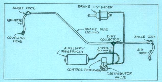
Single-pipe System
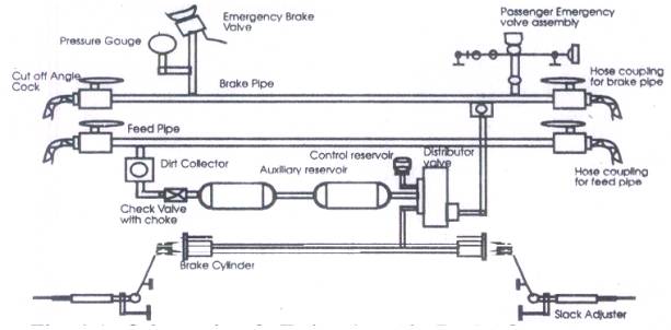
Twin-pipe System
Comparison of single-pipe and twin-pipe systems
| Parameters | Single Pipe | Twin Pipe |
|---|---|---|
| Principle of operation | The operation is same as that of the twin pipe system except that the auxiliary reservoir is charged through the D.V. instead of feed pipe, since there is no feed pipe in single pipe system. | The Brake pipe is charged to 5kg/cm2 by the driver's brake valve. The auxiliary reservoir is charged by the feed pipe at 6kg/cm2 through a check valve and choke. The brake cylinder is connected to the atmosphere through a hole in the D.V. when brakes are under fully released condition. To apply brakes, the driver moves automatic brake valve handle either in steps for a graduated application or in one stroke to the extreme position for emergency application. By this movement the brake pipe pressure is reduced and the pressure differenced is sensed by the D.V. against the reference pressure locked in the control reservoir. Air from the auxiliary reservoir enter the brake cylinder and the brakes are applied.At the time of release the air in the brake cylinder is vented progressively depending upon the increase in the brake pipe pressure. When the brake pipe pressure reaches 4.8kg/cm2 the brake cylinder is completely exhausted and brakes are fully released. |
| Charging auxiliary reservoir | Discontinued during brake application | Uninterrupted |
| B.C. and A.R. pressure equalisation | Occurs during prolonged brake application | Does not occur |
| Release of brakes (reduction in brake cylinder pressure) | Proportionate to build up of A.R pressure | Auxiliary reservoir is continuously charged through feed pipe |
| Leakage in brake cylinder during application | During emergency application, feed for auxiliary reservoir from brake pipe is discontinued. Leakages in brake cylinder will therefore reduce braking force since auxiliary reservoir may not be able to equalise the leakages. | Auxiliary reservoir is continuously charged through feed pipe and hence leakages in brake cylinder can be equalised even during emergency application ensuring full brake force. |
| Colour | Brake pipe - Green Feed pipe - White |
|
| Pressure | Brake pipe - 5kg/cm2 | Brake pipe - 5kg/cm2 Feed pipe- 6kg/cm2 |
Comparison of conventional and bogie-mounted air brakes
| Parameters | Conventional Air Brakes | Bogie-mounted Air Brakes |
|---|---|---|
| Bogie cylinder mounting location | Underframe | Bogie frame |
| No. of air brake cylinders / coach | 2 | 4 |
| Size of cylinder | 14" | 8" |
| Slack adjuster | External | Integral with the air brake cylinder |
| Brake block | Conventional | High friction 'K' type composite block |
Material provided by S Krishnamorthy, Copyright 2002.