Auxiliary Machines and Equipments in Electric Locomotives
by Khalid Kagzi, 2007
- Introduction
- Transformer Auxiliaries
- Rectifier Block Auxiliaries
- Smoothing Reactor Auxiliaries
- Traction Motor Auxiliaries
- Other Auxiliaries
- Switching Sequence
- Power Supply
Electric locos derive tractive effort from Traction Motors which are usually placed in the bogie of the locomotive. Usually one motor is provided per axle but in some older generation of locos two axles were driven by a single Traction Motor also.
However apart from Traction Motors, many other motors and equipments are provided in electric locos. These motors are collectively known as the Auxiliaries. The aim of this article is to provide an insight into the various Auxiliary Machines provided in the Electric Locos operational on the Indian Railways.
But to understand the reasons why these auxiliaries are needed, it is necessary to understand the manner in which the electric locos operate. An important part of the electric loco is the Power Circuit. A short description of the power circuit of Electric Locos operational on the Indian Railways can be seen here. The article referred to describes the main components of the Power Circuit of the Electric Locomotive comprising of the following parts:
- Transformer (including Tap-Changer)
- Rectifier
- Smoothing Reactor
- Traction Motors
- Main Starting Resistances (in DC Traction on Dual Power Locos only)
- Dynamic Braking Resistance Cooling Blower
A common feature running through all the above electrical equipments is that all of these generate a lot of heat during their normal operation. Even when they are not in use, they might generate a nominal amount of heat. Normally any electrical equipment generates heat as by-product during operation. But traction vehicles tend to generate more heat than normal. This is because day-by-day the demand on traction vehicles is increasing. But an increase in the power output more or less translates into increased size of the relevent equipments too. But a major problem with traction vehicles is that you cannot increase their size beyond a certain limit. This is due to "Loading Guage Restrictions". Hence, the power output of the locomotives has to be increased indirectly without increasing their size. This is done by "pumping"more power through the equipments and cooling them at a suitable rate at the same time.
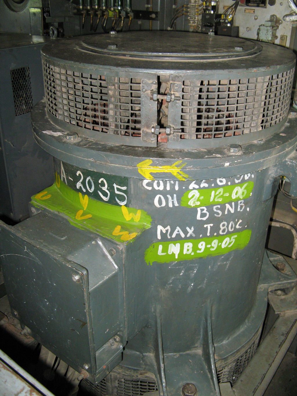
Hence the different auxiliaries provided for cooling and other purposes in these locos is described below. All the motors are of the AC 3 Phase squirrel cage induction type and require very little maintenance and are simple and robust. They are described with regard to their relationship to the major power equipments
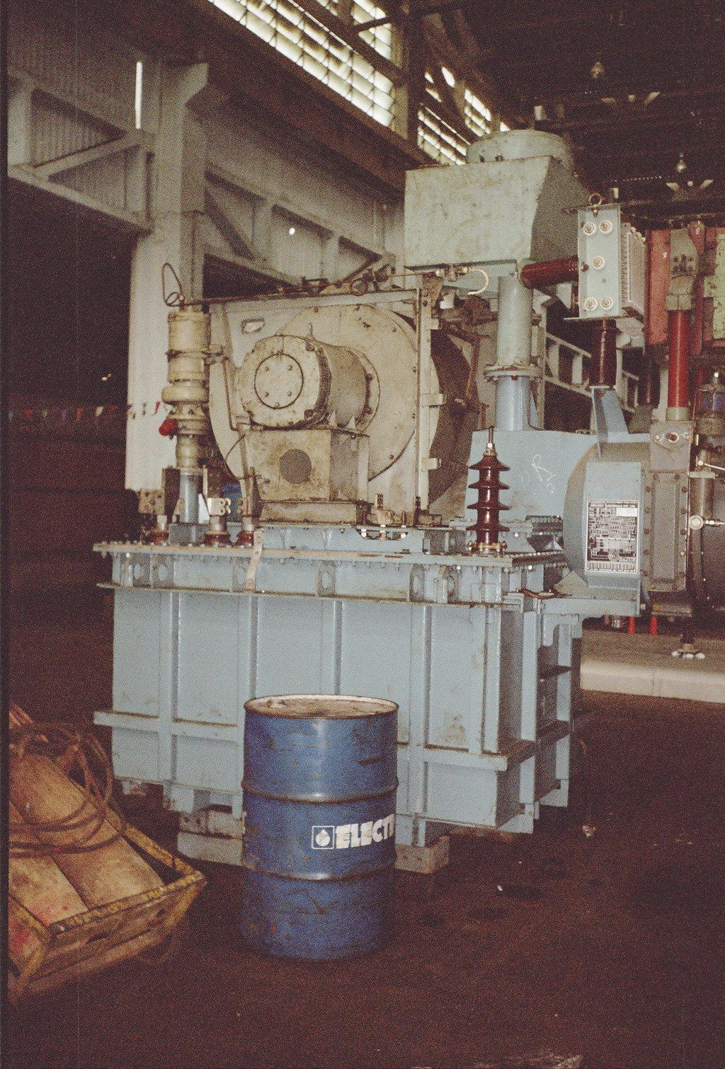
Auxiliaries of the Transformer
Transformer Oil Circulating Pump (MPH)
The transformer tank is filled with oil which serves two purposes. It provides enhanced insulation to the transformer and its surroundings and the oil absorbs the heat generated in the transformer and takes it away to the Transformer Oil Cooling Radiator. The circulation of this oil is carried out by the MPH.
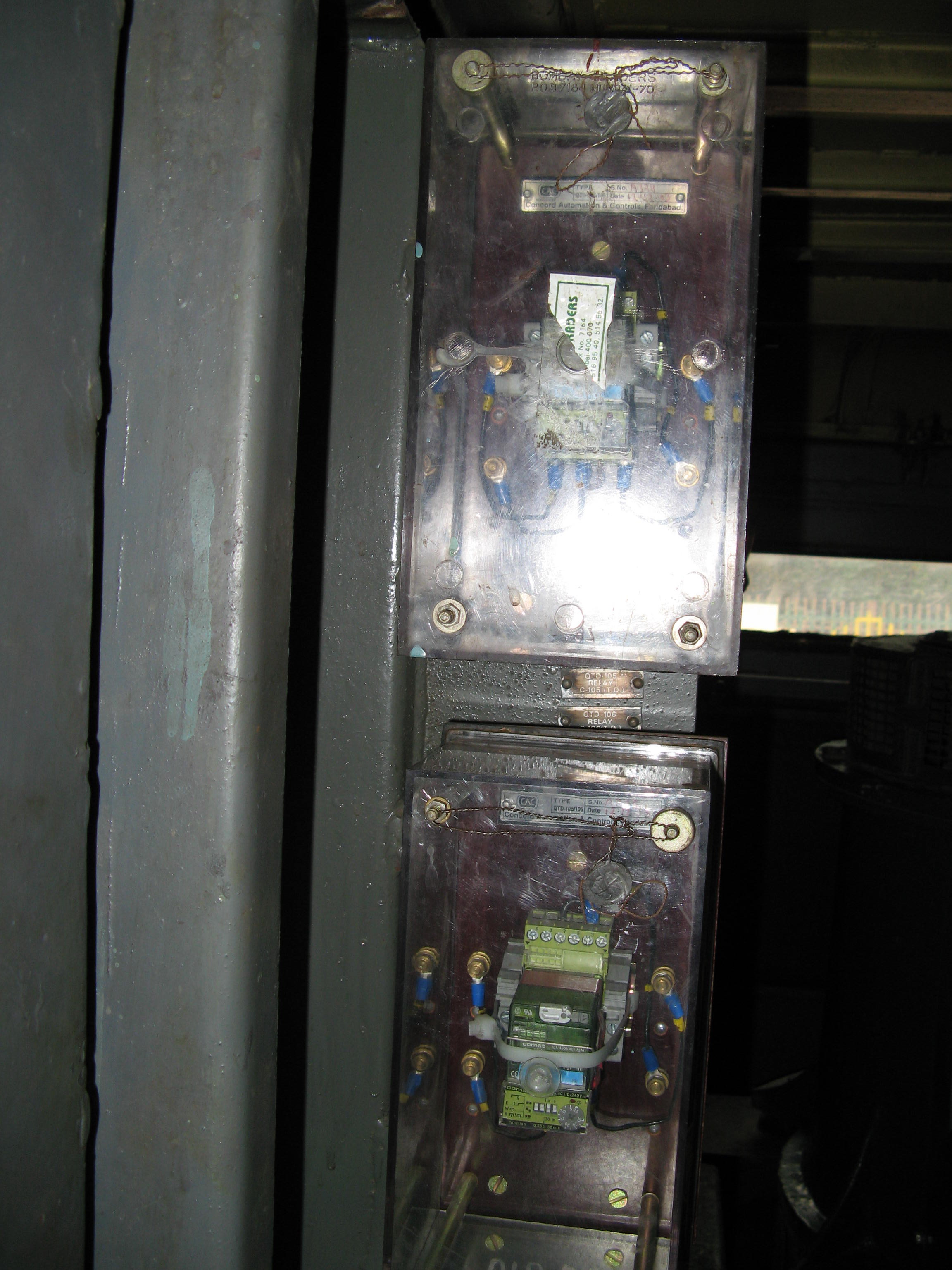
A flow valve with an electrical contact is provided in the oil circulating pipe. As long as the oil is circulating properly, the contacts on the relay remain closed. However, in case the MPH fails or stops the relay contacts open which in turn trips master auxiliary protection relay Q-118. This trips the main circuit-breaker(DJ) of the loco. Thus the transformer is protected.
Transformer Oil Cooling Radiator Blower (MVRH)
The MPH circulates the transformer oil through a radiator array on top of the transformer. Air is blown over the radiator by the MVRH. This discharges the heat from the radiator into the atmosphere. A flow detecting relay is provided in the air-stream of the MVRH. The flow detector is a diaphragm type device. The flow of air presses the diaphragm which closes an electrical contact. This relay is known as the QVRH. In case the MVRH blower fails the the QVRH releases and trips the DJ through the relay Q-118.
Auxiliaries of the Rectifier Block (RSI 1 & 2)
Rectifier Cooling Blowers-MVSI-1 and MVSI-2
One blower is provided for each of the rectifier blocks. As rectifiers are semiconductor devices, they are very sensitive to heat and hence must be cooled continously. The switching sequence of the MVSI blowers is setup in such a way that unless the blowers are running, traction cannot be achieved. A detection relay of diaphragm type is also provided in the air stream of these blowers. However, the detection relay (QVSI-1 & 2)are interlocked with a different relay known as Q-44. This is a much faster acting relay with a time delay of only 0.6 seconds. Hence the failure of a MVSI blower would trip the DJ in less than 1 second.
Auxiliaries of the Smoothing Reactors (MVSL 1 & 2)
In WAM-4 locos only one MVSL blower is provided for the cooling of the Smoothing Reactors SL 1 & 2. However in WAG-5 and other locos two blowers namely MVSL 1&2 are provided for each of the SL's. Their running is "proved*"by the Q-118 relay.
*In railway parlance Proving means to verify whether an equipment or device is working properly.
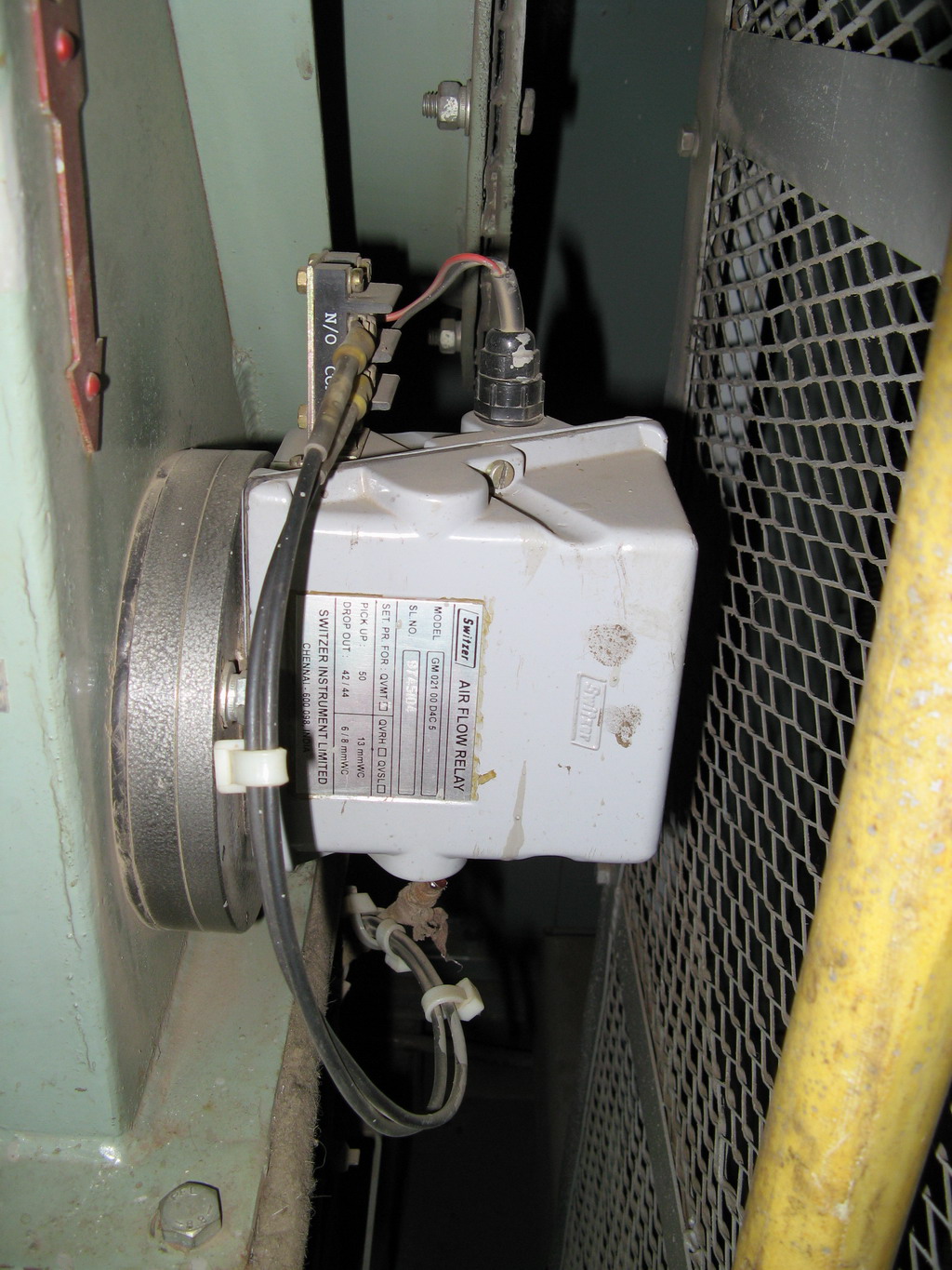
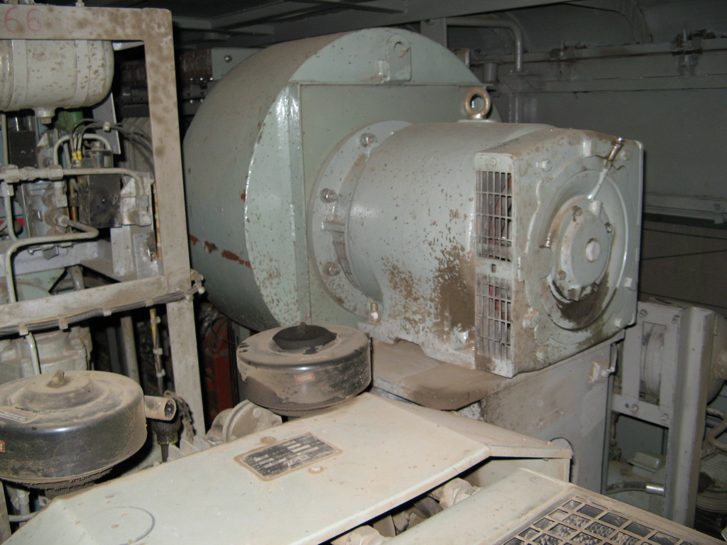
Auxiliaries of Traction Motors (MVMT 1 & 2)
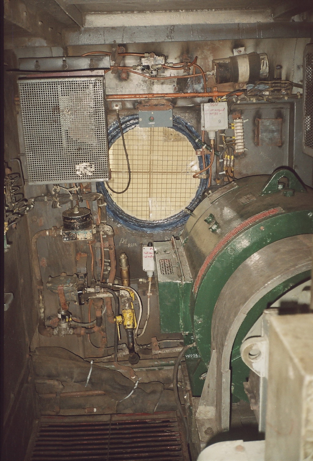
In the course of normal operation the traction motors also generate a lot of heat. This heat is dissipated by two blowers namely MVMT 1 & 2 which force air through a duct into the traction motors of Bogie-1 namely TM-1, TM-2, TM-3 and Bogie-2 namely TM-4, 5, 6 respectively. The traction motor cooling blowers require a large quantity of air which is taken from vents in the side-wall of the loco. Body-side filters are provided to minimise the ingress of dust into the loco. Their running is detected by Air-Flow sensing relay QVMT 1 & 2 (Pic-2) which in turn give there feed to the Q-118 relay.
Other Auxiliaries
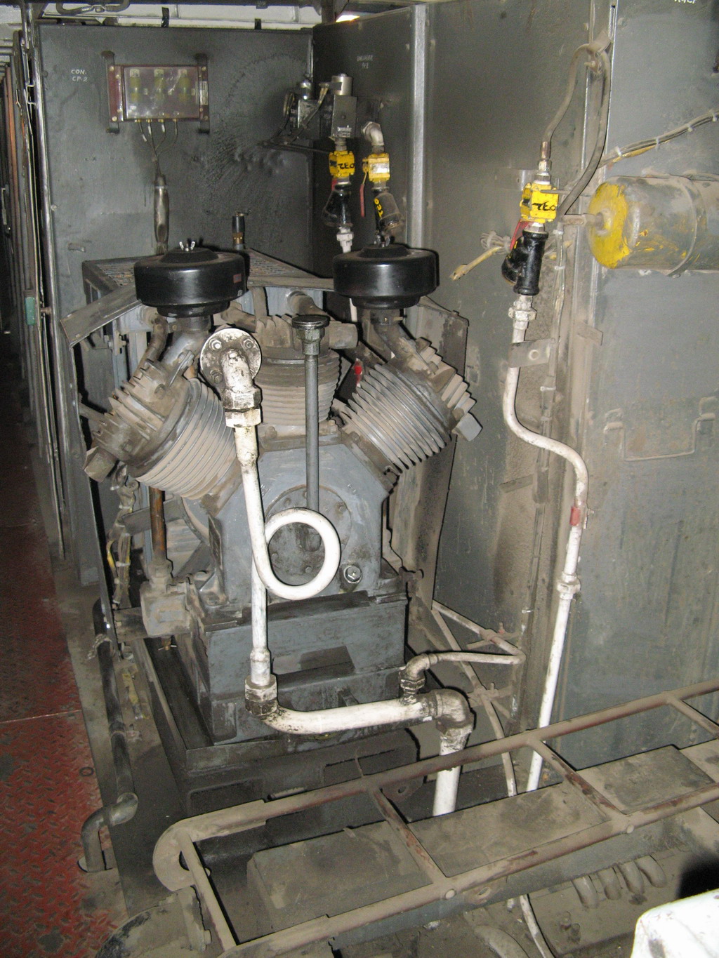
Air Compressors (MCP 1, MCP-2, MCP-3)
Electric locos need compressed at a pressure ranging from 6 kg/cm2 to 10 kg/cm2. Compressed air is used for the loco's own air brake system as also for the train brakes, for raising the pantograph, for operating the power switchgear inside the loco such as the power contactors, change-over switches, windscreen wipers, sanders, etc.
This compressed air is obtained by providing three air compressors, each having a capacity to pump 1000 litres of air per minute. However depending on the current requirement, more than two compressors are rarely needed.
Vacuum Pumps (MPV 1 & 2)
In locos equipped to haul vacuum braked trains, two vacuum pumps are also provided of which at least one is running in normal service and sometimes both may have to be run if train brakes are required to be released in a hurry.
Dynamic Braking resistance Cooling Blower (MVRF)
In locos equipped with internal dynamic braking resistances, MVRF blower is provided for cooling the resistances during braking. While all the Auxiliary machines run on the power supply provided by the Arno convertor / Static Convertor / Motor-Alternator set, the MVRF blower runs off the supply derived from the output of the Traction Motor itself and is connected in parallel to the Dynamic Braking Resistances.
Main Starting Resistance Cooling Blowers (MVMSR)
These blowers(four in number)are provided in WCAM-1, WCAM-2, WCAM-3 locos and are used during DC line working to cool the Main Starting Resistances(MSR). The MSR is used for regulating the voltage supplied to the Traction Motors during DC line working and carry the whole current of the traction motors which results in a lot of heat generation which must be continously dissipated. The working of the MVMSR's is also proved by respective sensing relays(QVMSR's) of the diaphragm type which in turn are interlocked with the relay Q-118 in the manner described later in this article.
Switching and operational sequence
The auxiliary machines mentioned above are energised as per the requirements in the loco. Some of them are run continously while some may only be required intermittanly while in rare cases, some may not be required at all during the whole run of the loco. Also the working sequences of the same auxiliary machines may differ across different models of locomotives as also in different working environments. For the purpose of this article, I've described the switching sequences of the WAG-5 loco except for the case of dual power locos such as the WCAM-1, WCAM-2, WCAM-3 which will be described seperately.
It should be kept in mind that all the above mentioned machines are of large horsepower and hence consume a lot of power and draw a lot of current from the power supply. In addition when any motor starts, initially it draws a current which may be up to 3-10 times its normal current. Hence, if all the motors or even a few motors are started simultaneously, it would cause a tremendous demand on the power supply in terms of the current drawn. This might also cause the power supply to trip because the supply is only equipped to deal with the normal running current of the machines and not such a huge current. To prevent such a situation, the starting of some of the motors is staggered which prevents heavy load currents from being drawn.
In the following table the starting and running sequence of the auxiliary machines is laid out:
| AUXILIARY | STARTS (CONTACTOR NO.) |
PROGRAM SWITCH | PROGRAM SWITCH POSITION 0 | PROGRAM SWITCH POSITION 1 | PROGRAM SWITCH POSITION 2 | PROGRAM SWITCH POSITION 3 | REMARKS |
|---|---|---|---|---|---|---|---|
| MPH | On DJ being closed (Direct supply from Three-Phase Busbar via HPH) |
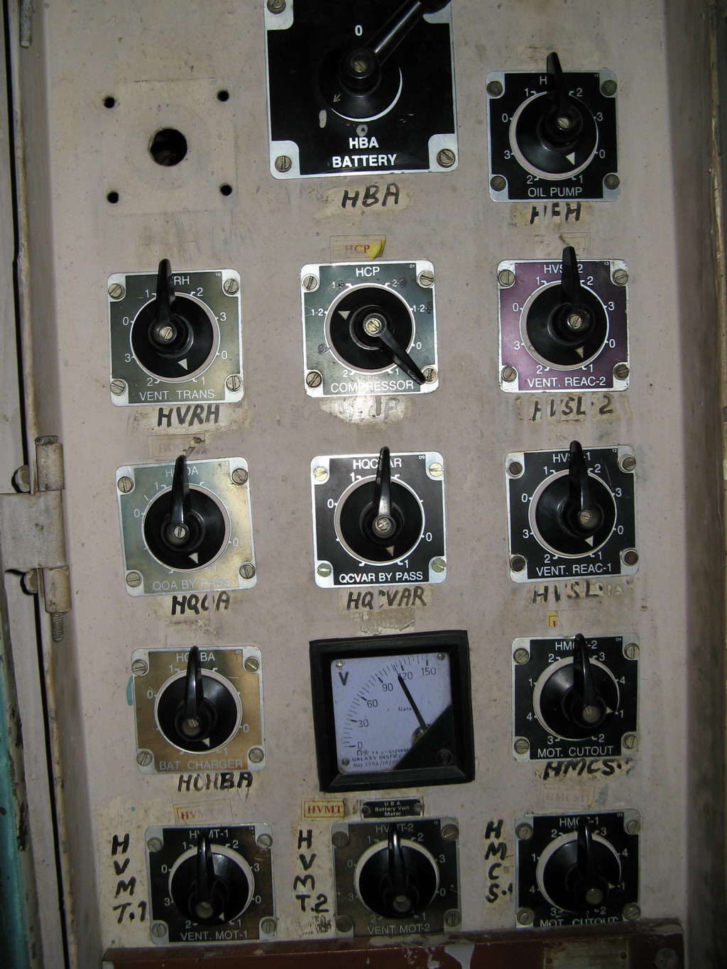
HPH (Provided on the Auxiliary panel) |
OFF | Normal Running | Motor isolated and detecting relay in circuit | Motor running and detecting relay isolated | |
| MVRH | MPJ in Forward/Reverse or BLVMT � being closed (C-107) |
HVRH (Provided on the Auxiliary panel) |
OFF | Normal Running | Motor isolated and detecting relay in circuit | Motor running and detecting relay isolated | |
| MVSI 1&2 | On DJ being closed (Direct supply from Three-Phase Busbar via HVSI 1&2) |
HVSI 1&2 (Provided on respective RSI block itself) |
OFF (Traction Motors also isolated) |
Normal Running | Motor isolated and detecting relay in circuit | Motor running and detecting relay isolated | |
| MVSL 1&2 | On DJ being closed (Direct supply from Three-Phase Busbar via HVSL) |
HVSL 1&2 | OFF | Normal Running | Motor isolated and detecting relay in circuit | Motor running and detecting relay isolated | |
| MVMT 1 | Five seconds after MVRH starting (C-105) |
HVMT 1 (Provided on the Auxiliary panel) |
OFF | Normal Running | Motor isolated and detecting relay in circuit | Motor running and detecting relay isolated | |
| MVMT 2 | Five seconds after MVMT-1 starting (C-105) |
HVMT 2 (Provided on the Auxiliary panel) |
OFF | Normal Running | Motor isolated and detecting relay in circuit | Motor running and detecting relay isolated | |
| MCP-1, MCP-2, MCP-3 | On closing BLCP/BLCPD/RGCP (C-101, C-102, C-103) | HCP (Provided on the Auxiliary panel) |
OFF | HCP at position-1 - MCP 1/2/3 running HCP at position-2 - MCP 2/3 running HCP at position-3 - MCP 1/3 running (In dual-brake locos, an interlock is provided wherein only one compressor can be run if the Vacuum Exhauster is running while working vacuum braked trains. In such cases compressed air is needed only for the loco and one compressor is sufficient for the purpose and also prevents excess load on the power supply system). |
RGCP is the auto pressure switch which normally regulates the running of the compressors | ||
| MPV-1, MPV-2 | On closing BLPV (C111/C112 for low speed and C121 and C122 for high speed) |
ZPV and other brake interlocks | OFF | ||||
| MVRF (In locos provided with internal DBR) |
On the initiation of dynamic braking from master controller (Is in parallel with the DBR load resistances and also constitutes part of the load on the traction motors) |
Normal Running | Motor isolated and detecting relay in circuit | Motor running and detecting relay isolated | New locos being turned out by CLW have a three-phase motor to run the MVRF blower and it takes supply from the Static Convertor. | ||
| MVMSR-1-4 (In dual power locos only) |
On DS being closed | HVMSR 1 and 2 (Provided on the Auxiliary panel) |
OFF | Normal Running | Motor isolated and detecting relay in circuit | Motor running and detecting relay isolated | |
Note: The control circuit of MVMSR has been modified in WCAM-1 locos and HVMSR switches have been removed.In case of failure of any MVMSR, the loco must be declared failed. However the same loco in this condition may be energized and run normally in AC line working.
Power Supply
Depending on the locomotive, power for the auxiliary machines is obtained through three different methods. A separate power supply arrangement is needed because the motors require three phase supply while the OHE supply is of the single phase type. So the main requirement of the power supply for the auxiliary machines is for a device which can convert single phase AC into three phase AC. It becomes a little more complicated for the dual power locomotives such as the WCAM-1, WCAM-2, WCAM-3.
The three main types of equipments used to supply power to the auxiliaries are discussed below.
Arno Convertor
This is a rotary convertor which has a combined set of windings and is used to convert the single phase supply from the Tertiary winding of the Loco transformer to Three-Phase AC which is fit for use by the various Auxiliary machines in the loco.
The Arno is basically a split-phase induction motor with an additional winding on the stator for the generating phase. In an induction motor the rotating field of the stator creates a corresponding field in the rotor squirrel cage too which causes the rotor to start rotating at "slip" speed which is slightly less than the speed at which the stator field is rotating. However, this rotating field of the rotor is additionally utilized in the arno to create power in the generating phase winding which gives the three phase output of the arno convertor. In the stator winding of the arno, the motoring phases carry the load as well supply currents of the arno in opposite direction which causes a net reduction in the actual current carried by the windings in the stator but the generating phase carries only the load current which causes a voltage drop in the generating phase. To counteract this, up to 20% more turns are provided in the generating phase winding.
See Reference 1 listed below for more details.
Precautions during arno starting
The Arno starts as a split-phase induction motor by inserting a resistance momentarily in the generating phase winding as shown in the diagram above. This starting resistance must be removed as the rotor approaches 90% of its normal speed. If this resistance is left in the circuit, it can cause heating of the generating phase winding and excessive vibrations. If the starting resistance is removed prematurely it can take longer for the arno to reach synchronous speed. Hence, to maintain proper timing two methods could be employed-either measure the speed of the arno by attaching a tacho-generator or measure the output voltage of the generating phase.
The voltage measurement method has been found to be more effective and is used in this system. The voltage between the generating phase and the neutral of the arno convertor remains at a low value till just before the arno reaches its synchronous speed when it reaches its full value and is measured by the relay named QCVAR. It picks up when the voltage rises to near maximum value. The energisation of the QCVAR causes the starting contactor C-118 to open which disconnects the starting resistance. The normally open (NO) contacts of the QCVAR are also interlocked with the Q-118 relay. This interlock is used to ensure that if the QCVAR fails to operate within 5 seconds, the Q-118 interlock trips the DJ. A bypass switch named HQCVAR is also provided which can be used to bypass the HQCVAR relay in the Q-118 branch so that DJ tripping does not occur but in such a case the Arno must be monitored continuously to ensure that its not overheating.
Static Invertor
The Arno convertor suffers from various disadvantages chief of which is output voltage imbalance which can cause heating up of the auxiliary motors, varying output voltage because of the variations in OHE voltage, problems related to starting of the Arno, etc. To overcome these shortcomings and to improve loco reliability, the Indian Railways have started providing Static Invertor power supply for auxiliary machines in locomotives.
See Reference 2 listed below for more details.
The Static Invertor comprises a force commutated rectifier, a DC link and an Invertor which is usually composed of six IGBT switches.
The Static Invertor broadly works in the following manner:
The supply from the transformer tertiary winding is fed into the rectifier of the Invertor which is force commutated and is usually composed of IGBTs. The rectified supply is fed into the DC link which is a large capacitor and is charged by the DC supply. The DC link also has an inductor to suppress the AC ripple left over from the rectification cycle and harmonics generated by the invertor. Additionally the DC link maintains the supply to the invertor in case of temporary supply failure and also absorbs transient voltages generated during switching heavy loads. In some models if the Static Invertor, an IGBT type switch is provided which is used to switch the DC link in and out of the circuit as per requirement.
The DC from the rectifier/DC link is converted into three phase AC by the Invertor module by switching the IGBTs in proper sequence which creates a near sine wave AC displaced by 120 degrees. Voltage control is achieved by the Pulse Width Control (PWM) method. This ensures that the output voltage of the Static Invertor is near constant irrespective of the input voltage from the transformer.
Apart from improving the reliability of the power supply system, one of the most important advantages of the Static Invertor is that it has considerably reduced Auxiliary Motor burnouts due drastic improvement in the power quality in terms of voltage.
Additionally the Static Invertor also detects earth faults, single phasing and overloading hence these functions are no longer needed to be monitored by external devices.
An electronic control system is provided which monitors the complete functioning of the Static Invertor. The control system gives the gate firing impulses to the various IGBTs and also controls the phase angle of the firing pulse to ensure proper phase sequencing. In addition it monitors the Static Invertor for internal and external faults.
Motor-Alternator Set (used only in the WCAM-1 and the WCG-2 locos)
The MA set is used to generate power for the Auxiliary machines in both the AC as well as DC sections because the Arno cannot run in DC line supply. The MA set comprises of a DC motor coupled to an AC alternator by a mechanical coupling. When the loco is under AC line supply the DC motor of the MA Set is fed by the tertiary winding of the transformer via an auxiliary rectifier known as RSI-3. While running in DC line sections the DC motor of the MA Set is supplied directly by the OHE line supply. The switching between the AC and DC modes is determined automatically by the position of the Panto changeover switch ZPT which in turn determines the position of the Change-Over switches.
A stable AC supply output consists of two main parameters namely the frequency and the voltage. The frequency of the output supply is directly dependent on the speed at which the alternator is running and the output voltage is dependent on the field excitation voltage of the alternator. Generator speed tends to fall as the electrical load on the generator increases and vice-versa. To keep the speed of the alternator near constant a frequency regulator is provided which continously monitors the frequency and as per requirement controls the speed of the alternator by reducing or increasing the field excitation of the DC motor. A bypass switch for the frequency regulator is also provided in case the FRG becomes defective.
References
- Modern Electric Traction by H Partab published by m/s Dhanpat Rai and Sons, Delhi
- A Project report on Development of Static Converter in Conventional Locos, By GP Mandal, IRIEEN-Nasik Road-Maharashtra.